For our DIY Weather Station, we’ve built our sensor housings and run power and internet out to the data logger site. It’s time to install the data logger and hook up our sensors. Thankfully, this is much easier than getting power and internet to the site. First, let’s take a look at what we need to ensure we have all the materials on hand. I am planning to add more sensors in the future. For now we are only adding sensors for temperature, humidity, and barometric pressure.
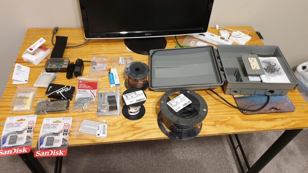
Supplies Needed
- Raspberry Pi, with case and power adapter
- GPIO Ribbon Cable for the Raspberry Pi, which makes it easier to connect the sensors.
- MPL3115A2 I2C Barometric Pressure, Altitude, and Temperature Sensor
- AM2302 Wired Temperature/Humidity Sensor
- 22 AWG Wire Jumpers, to connect the sensors to the Raspberry Pi
- Thermostat Wire
- Breadboard for Testing (optional)
Do a Test Run Inside First
Before installing everything at the data logger site, I always do a test run in a controlled environment indoors first. I set everything up in my home office, which allowed me to spread everything out. I could confirm that I hooked everything up correctly, and easily troubleshoot any issues. As a nice bonus, it let me work in the air conditioning instead of outside in this 100-plus degree heat.
First, get the Raspberry Pi up and running. The Pi will come with instructions for how to install the Raspbian operating system, which is a distribution of Debian Linux. After installing the operating system, simply plug in an external monitor and an ethernet cable. Then plug the Raspberry Pi in to turn it on. Once it boots up, log in and make sure you can get online and open a Terminal window.
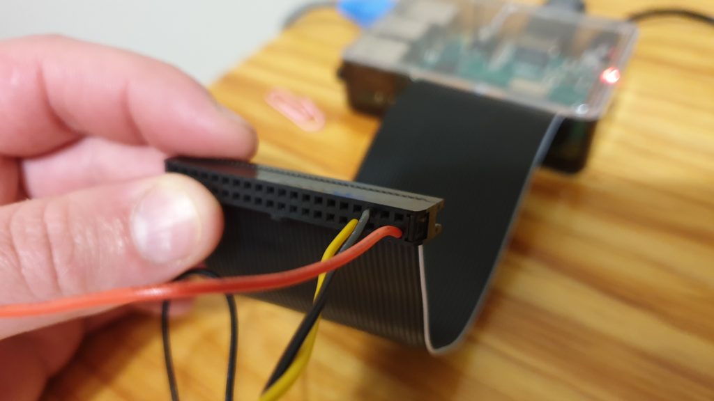
Before connecting any sensors, shut down the Pi and unplug it. Never attempt to connect any sensors to the Pi while it is powered on! If you connect them to the wrong ports, you can damage both the sensor and the Pi by either running incorrect voltage through it or by shorting it out. After shutting down and unplugging the Raspberry Pi, connect the GPIO ribbon cable. Then get your sensors and jumper wires ready.
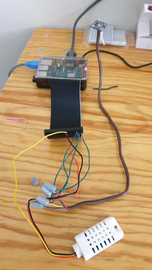
Each sensor will have instructions for which GPIO pin it needs to be connected to. Most sensors will connect to either 3 or 4 GPIO pins. One pin feeds the hot and neutral wires for power, and the remaining pins transfer data. For testing the sensor, connect the sensor to the GPIO pin with the jumper wires. If the sensor has wires built into it, which our temperature/humidity sensor does, you can use those.
A Few Tips for Connecting the Sensors
- Most sensors support using both 3.3 Volts and 5 Volts for power. For this test (and any other application where you are using short lengths of wire), always use 3.3 Volts. You may damage the sensor if you use 5 volts. Only use 5 volts is you have long lengths of wire. Unfortunately the definition of “long” varies depending on what type of sensor you’re using.
- Each sensor will come with instructions telling you which GPIO pin to connect it to. Please be aware that if you’re using a GPIO ribbon, those pins will be a mirror image of the GPIO pin diagram that comes with the Raspberry Pi. If you’re connecting the sensor directly to the pins on the Pi’s board (i.e. not using a GPIO ribbon), that diagram will be correct.
Once you have the sensor(s) connected, it’s time to test them, so power the Pi back on.
Test the Sensor After Connecting It
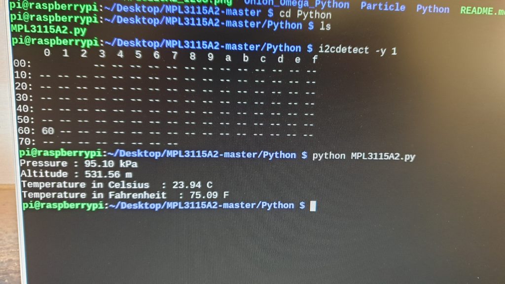
Most sensors come with scripts so you can verify that they’re working. Both sensors I’m connecting to the data logger come with Python scripts for testing, which I downloaded from GitHub. After installing any dependencies those scripts require, run the test script in a Terminal window. If the sensors are connected correctly, the sensor readings will appear in the Terminal window’s output. Make sure the sensor readings are accurate, too! If you’re in the United States, be aware that nearly all test scripts will output sensor readings in metric units by default.
Tip #1: Once you have verified the sensors are working correctly, I highly recommend taking a picture of the GPIO ribbon that shows each sensor wire connections. That way you can easily re-create the setup when you move it to the permanent data logger site.
Tip #2: Before you move the Pi to the permanent data logger site, enable SSH logins and turn off the GUI so it will be command line only. I don’t have an easy way to get a monitor to the data logger site so it is much easier to just SSH into the Pi from my laptop over my local network.
Installing the System at the Data Logger Site
Now that we’ve confirmed the sensors are working, it’s time to permanently install them at the data logger site. Make sure you shut down and power off the Pi before unplugging any sensors to move them.
A Quick Note About Thermostat Wire
I chose to use thermostat wire to connect the sensors. It is made out of a high-quality, highly conductive metal (solid copper). The conductors in thermostat wire are the perfect size for connecting to the sensors and the Raspberry Pi. It comes in many different configurations (number of conductors). It’s also cost-effective and won’t break the bank.
For the DIY weather station project, I used 18/5 (18 gauge, 5 conductors inside) wire because the pressure sensor has four connections. 18/3 wire would work fine for the temperature/humidity sensor, which only has three connections. For more complex sensor configurations, I have seen thermostat wire with up to 9 conductors available at most hardware stores.
Installing the Sensors
We are connecting two sensors to the data logger here: the temperature/humidity sensor and the barometric pressure sensor. We will mount the barometric pressure sensor in the data logger housing with the Raspberry Pi. It can be connected in the same manner it was for our inside test using a short piece of thermostat wire.
The temperature/humidity sensor is a little trickier, but if you’ve made it this far, it’s nothing you can’t handle. Before diving in, remove about 8 cm (3 in) of the jacket on the thermostat wire to reveal the conductor wires inside.
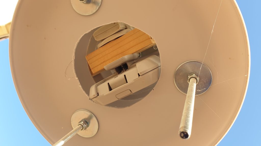
Put the Sensor in its Housing Before Connecting any Wires
The first step is to mount the sensor in the solar radiation shields we created in Part 1 of the DIY weather station project. I hung a small piece of wood in the radiation shield’s cavity and screwed the sensor to that. Make sure there is a hole in the top of the radiation shield to run the thermostat wire through. The hole should be just barely big enough to fit the wire through. After attaching the sensor to the wood, feed the end of the thermostat wire through the hole in the top of the radiation shield. Connect the sensor wires to the conductors of the thermostat wire using gray wire nuts. You can cut off any unused conductors in the thermostat wire or fold them back so they’re out of the way.
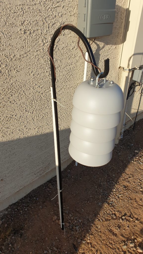
Next, securely run the thermostat wire back to where the data logger will be mounted. In my setup, I ran the wire through a conduit attached to the shepherd’s pole from which the radiation shield hung, then underground and up to the data logger through the same conduit through which the power and internet cables run.
An Important Note About Voltage and Wire Length
The DIY weather station’s analog temperature sensor can only support a maximum wire length of about 3.5 meters (11.5 ft). If you cannot get a sensor reading using 3.3 volts, use 5 volts instead. You’ll likely need to use 5 volts for wire lengths greater than about 1 meter. If you still cannot get a sensor reading using 5 volts, you’ll have to shorten the wire. By contrast, the digital pressure sensor can support a wire length up to approximately 30 meters (100 ft).
Installing the Data Logger
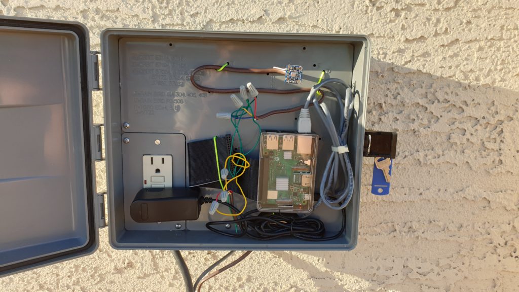
The data logger can be mounted in the sprinkler box housing we installed on the side of the house in Part 2 of this project. Run pieces of string through holes in the bottom of the Raspberry Pi’s case to attach it to the mount points inside the sprinkler box.
After mounting the Raspberry Pi, connect the sensor wires to their corresponding GPIO pins. If you have issues connecting the thermostat wire directly to the GPIO pins, connect one end of a jumper wire to the GPIO pin and attach the other end of the jumper wire to the sensor wire with a gray wire nut. After confirming the sensor wires are in place, connect the ethernet cable and plug the Raspberry Pi into the outlet in the sprinkler box to power it on. SSH into the Pi from your computer and run the test scripts again to confirm that the sensors are working properly.
Now that the sensors and data logger are in place, in the next phase we will set up the database, program the data logger to pull data from the sensor at specific intervals, and connect the data logger to the rest of the DIY weather station.